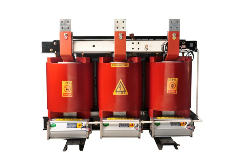
Oil-Immersed Power Transformers
The S11-M series fully sealed oil-immersed power transformers developed and produced by our company feature low loss, low noise, and high efficiency, achieving excellent energy-saving effects and reducing pollution. Compared with ordinary oil-immersed transformers, fully sealed transformers eliminate the need for an oil conservator. Oil volume changes are automatically compensated by the elasticity of the corrugated oil tank's bellows, isolating the transformer from air, preventing and slowing oil deterioration and insulation aging, enhancing operational reliability, and requiring no maintenance during normal operation.
Model: S11-M □ / □
| Model | Rated capacity (kVA). | Connection group label | High voltage (kV). | Branch Coverage (%) | Low voltage (kV). | No-load loss (W). | Load loss (W). | No-load current (%) | Short-circuit impedance (%) |
|---|---|---|---|---|---|---|---|---|---|
| S11-M-30 | 30 | Yyn0 or Dyn11 | 6、6.3、10、10.5 | 15% or ±2×2.5 | %.0.4 | 100 | 630/600 | 1.5 | 4.0 |
| S11-M-50 | 50 | Yyn0 or Dyn11 | 6、6.3、10、10.5 | 15% or ±2×2.5 | %.0.4 | 130 | 910/870 | 1.3 | 4.0 |
| S11-M-63 | 63 | Yyn0 or Dyn11 | 6、6.3、10、10.5 | 15% or ±2×2.5 | %.0.4 | 150 | 1090/1040 | 1.2 | 4.0 |
| S11-M-80 | 80 | Yyn0 or Dyn11 | 6、6.3、10、10.5 | 15% or ±2×2.5 | %.0.4 | 180 | 1310/1250 | 1.2 | 4.0 |
| S11-M-100 | 100 | Yyn0 or Dyn11 | 6、6.3、10、10.5 | 15% or ±2×2.5 | %.0.4 | 200 | 1580/1500 | 1.1 | 4.0 |
| S11-M-125 | 125 | Yyn0 or Dyn11 | 6、6.3、10、10.5 | 15% or ±2×2.5 | %.0.4 | 240 | 1890/1800 | 1.1 | 4.0 |
| S11-M-160 | 160 | Yyn0 or Dyn11 | 6、6.3、10、10.5 | 15% or ±2×2.5 | %.0.4 | 280 | 2310/2200 | 1.0 | 4.0 |
| S11-M-200 | 200 | Yyn0 or Dyn11 | 6、6.3、10、10.5 | 15% or ±2×2.5 | %.0.4 | 340 | 2730/2600 | 1.0 | 4.0 |
| S11-M-250 | 250 | Yyn0 or Dyn11 | 6、6.3、10、10.5 | 15% or ±2×2.5 | %.0.4 | 400 | 3200/3050 | 0.90 | 4.0 |
| S11-M-315 | 315 | Yyn0 or Dyn11 | 6、6.3、10、10.5 | 15% or ±2×2.5 | %.0.4 | 480 | 3830/3650 | 0.90 | 4.0 |
| S11-M-400 | 400 | Yyn0 or Dyn11 | 6、6.3、10、10.5 | 15% or ±2×2.5 | %.0.4 | 570 | 4520/4300 | 0.80 | 4.0 |
| S11-M-500 | 500 | Yyn0 or Dyn11 | 6、6.3、10、10.5 | 15% or ±2×2.5 | %.0.4 | 680 | 5410/5100 | 0.80 | 4.0 |
| S11-M-630 | 630 | Yyn0 or Dyn11 | 6、6.3、10、10.5 | 15% or ±2×2.5 | %.0.4 | 810 | 6200 | 0.60 | 4.5 |
| S11-M-800 | 800 | Yyn0 or Dyn11 | 6、6.3、10、10.5 | 15% or ±2×2.5 | %.0.4 | 980 | 7500 | 0.60 | 4.5 |
| S11-M-1000 | 1000 | Yyn0 or Dyn11 | 6、6.3、10、10.5 | 15% or ±2×2.5 | %.0.4 | 1150 | 10300 | 0.60 | 4.5 |
| S11-M-1250 | 1250 | Yyn0 or Dyn11 | 6、6.3、10、10.5 | 15% or ±2×2.5 | %.0.4 | 1360 | 12000 | 0.50 | 4.5 |
| S11-M-1600 | 1600 | Yyn0 or Dyn11 | 6、6.3、10、10.5 | 15% or ±2×2.5 | %.0.4 | 1640 | 14500 | 0.50 | 4.5 |
| S11-M-2000 | 2000 | Yyn0 or Dyn11 | 6、6.3、10、10.5 | 15% or ±2×2.5 | %.0.4 | 1940 | 18300 | 0.40 | 5.0 |
| S11-M-2500 | 2500 | Yyn0 or Dyn11 | 6、6.3、10、10.5 | 15% or ±2×2.5 | %.0.4 | 2290 | 21200 | 0.40 | 5.0 |
Note: The load loss values above the slashes in the table apply to Dyn11 or Yzn11 connection groups, while those below the slashes apply to Yyn0.
| Model | Rated capacity (kVA). | Connection group label | High voltage (kV). | Branch Coverage (%) | Low voltage (kV). | No-load loss (W). | Load loss (W). | No-load current (%) | Short-circuit impedance (%) |
|---|---|---|---|---|---|---|---|---|---|
| S11-M-30 | 30 | Dyn11 | 20 | ±5% | 0.4 | 130 | 690 | 2.1 | 5.5 |
| S11-M-50 | 50 | Dyn11 | 20 | ±5% | 0.4 | 130 | 1010 | 2.0 | 5.5 |
| S11-M-63 | 63 | Dyn11 | 20 | ±5% | 0.4 | 150 | 1200 | 1.9 | 5.5 |
| S11-M-80 | 80 | Dyn11 | 20 | ±5% | 0.4 | 180 | 1440 | 1.8 | 5.5 |
| S11-M-100 | 100 | Dyn11 | 20 | ±5% | 0.4 | 200 | 1730 | 1.6 | 5.5 |
| S11-M-125 | 125 | Dyn11 | 20 | ±5% | 0.4 | 240 | 2080 | 1.5 | 5.5 |
| S11-M-160 | 160 | Dyn11 | 20 | ±5% | 0.4 | 290 | 2540 | 1.4 | 5.5 |
| S11-M-200 | 200 | Dyn11 | 20 | ±5% | 0.4 | 340 | 3000 | 1.3 | 5.5 |
| S11-M-250 | 250 | Dyn11 | 20 | ±5% | 0.4 | 400 | 3520 | 1.2 | 5.5 |
| S11-M-315 | 315 | Dyn11 | 20 | ±5% | 0.4 | 480 | 4210 | 1.1 | 5.5 |
| S11-M-400 | 400 | Dyn11 | 20 | ±5% | 0.4 | 570 | 4970 | 1.0 | 5.5 |
| S11-M-500 | 500 | Dyn11 | 20 | ±5% | 0.4 | 680 | 6940 | 1.0 | 5.5 |
| S11-M-630 | 630 | Dyn11 | 20 | ±5% | 0.4 | 810 | 6820 | 0.9 | 6.0 |
| S11-M-800 | 800 | Dyn11 | 20 | ±5% | 0.4 | 980 | 8250 | 1.8 | 6.0 |
| S11-M-1000 | 1000 | Dyn11 | 20 | ±5% | 0.4 | 1150 | 11330 | 0.7 | 6.0 |
| S11-M-1250 | 1250 | Dyn11 | 20 | ±5% | 0.4 | 1380 | 13200 | 0.7 | 6.0 |
| S11-M-1600 | 1600 | Dyn11 | 20 | ±5% | 0.4 | 1660 | 15950 | 0.6 | 6.0 |
| S11-M-2000 | 2000 | Dyn11 | 20 | ±5% | 0.4 | 1960 | 19140 | 0.6 | 6.0 |
| S11-M-2500 | 2500 | Dyn11 | 20 | ±5% | 0.4 | 2340 | 22220 | 0.5 | 6.0 |
Note: This 20KV transformer can be customized according to customer requirements, with dual-voltage wiring available on the high-voltage side. The transformer input can be switched using a selector switch based on the difference in network voltage between 20KV and 10KV.
| Voltage level (kV). | Maximum operating voltage (kV, RMS). | Rated short-term power frequency withstand voltage (kV, RMS) per minute | Rated lightning impulse withstand voltage (kV, peak value) Full-wave | Rated lightning impulse withstand voltage (kV, peak value) interception |
|---|---|---|---|---|
| 10 | 12 | 36 | 75 | 85 |
| 20 | 24 | 55 | 125 | 140 |
The S13 model is a product independently developed by our company based on the original S11 distribution transformer, combining research and application of new materials and processes, independent innovation, and technology introduction. Through the optimization and innovative design of the core and coil structure, it aims to reduce no-load losses and noise. No-load losses have dropped by an average of 20%. Noise levels have decreased by an average of 20% compared to the current national standard JB/T10088-2016, and product performance levels have reached advanced domestic levels.
Model: S13-M □ / □
| Model | Rated capacity (kVA). | Connection group label | High voltage (kV). | Branch Coverage (%) | Low voltage (kV). | No-load loss (W). | Load loss (W). | No-load current (%) | Short-circuit impedance (%) |
|---|---|---|---|---|---|---|---|---|---|
| S13-M-30 | 30 | Yyn0 or Dyn11 | 10.5、10、6.3、6 | ±5%、±2×2.5% | 0.4 | 80 | 630/600 | 1.5 | 4.0 |
| S13-M-50 | 50 | Yyn0 or Dyn11 | 10.5、10、6.3、6 | ±5%、±2×2.5% | 0.4 | 100 | 910/870 | 1.3 | 4.0 |
| S13-M-63 | 63 | Yyn0 or Dyn11 | 10.5、10、6.3、6 | ±5%、±2×2.5% | 0.4 | 110 | 1090/1040 | 1.2 | 4.0 |
| S13-M-80 | 80 | Yyn0 or Dyn11 | 10.5、10、6.3、6 | ±5%、±2×2.5% | 0.4 | 130 | 1310/1250 | 1.2 | 4.0 |
| S13-M-100 | 100 | Yyn0 or Dyn11 | 10.5、10、6.3、6 | ±5%、±2×2.5% | 0.4 | 150 | 1580/1500 | 1.1 | 4.0 |
| S13-M-125 | 125 | Yyn0 or Dyn11 | 10.5、10、6.3、6 | ±5%、±2×2.5% | 0.4 | 170 | 1890/1800 | 1.1 | 4.0 |
| S13-M-160 | 160 | Yyn0 or Dyn11 | 10.5、10、6.3、6 | ±5%、±2×2.5% | 0.4 | 200 | 2310/2200 | 1.0 | 4.0 |
| S13-M-200 | 200 | Yyn0 or Dyn11 | 10.5、10、6.3、6 | ±5%、±2×2.5% | 0.4 | 240 | 2730/2600 | 1.0 | 4.0 |
| S13-M-250 | 250 | Yyn0 or Dyn11 | 10.5、10、6.3、6 | ±5%、±2×2.5% | 0.4 | 280 | 3200/3050 | 0.90 | 4.0 |
| S13-M-315 | 315 | Yyn0 or Dyn11 | 10.5、10、6.3、6 | ±5%、±2×2.5% | 0.4 | 340 | 3830/3550 | 0.90 | 4.0 |
| S13-M-400 | 400 | Yyn0 or Dyn11 | 10.5、10、6.3、6 | ±5%、±2×2.5% | 0.4 | 410 | 4520/4300 | 0.80 | 4.0 |
| S13-M-500 | 500 | Yyn0 or Dyn11 | 10.5、10、6.3、6 | ±5%、±2×2.5% | 0.4 | 480 | 5410/5150 | 0.80 | 4.0 |
| S13-M-630 | 630 | Yyn0 or Dyn11 | 10.5、10、6.3、6 | ±5%、±2×2.5% | 0.4 | 570 | 6200/6200 | 0.60 | 4.5 |
| S13-M-800 | 800 | Yyn0 or Dyn11 | 10.5、10、6.3、6 | ±5%、±2×2.5% | 0.4 | 700 | 7500/7500 | 0.60 | 4.5 |
| S13-M-1000 | 1000 | Yyn0 or Dyn11 | 10.5、10、6.3、6 | ±5%、±2×2.5% | 0.4 | 830 | 10300/10300 | 0.60 | 4.5 |
| S13-M-1250 | 1250 | Yyn0 or Dyn11 | 10.5、10、6.3、6 | ±5%、±2×2.5% | 0.4 | 970 | 12000/12000 | 0.50 | 4.5 |
| S13-M-1600 | 1600 | Yyn0 or Dyn11 | 10.5、10、6.3、6 | ±5%、±2×2.5% | 0.4 | 1170 | 14500/14500 | 0.50 | 4.5 |
| S13-M-2000 | 2000 | Yyn0 or Dyn11 | 10.5、10、6.3、6 | ±5%、±2×2.5% | 0.4 | 1550 | 18300/18300 | 0.40 | 5.0 |
| S13-M-2500 | 2500 | Yyn0 or Dyn11 | 10.5、10、6.3、6 | ±5%、±2×2.5% | 0.4 | 1830 | 21200/21200 | 0.40 | 5.0 |
Tell us about your application and requirements — our team will help you specify the right product.